Mechanical Gd T Drawing

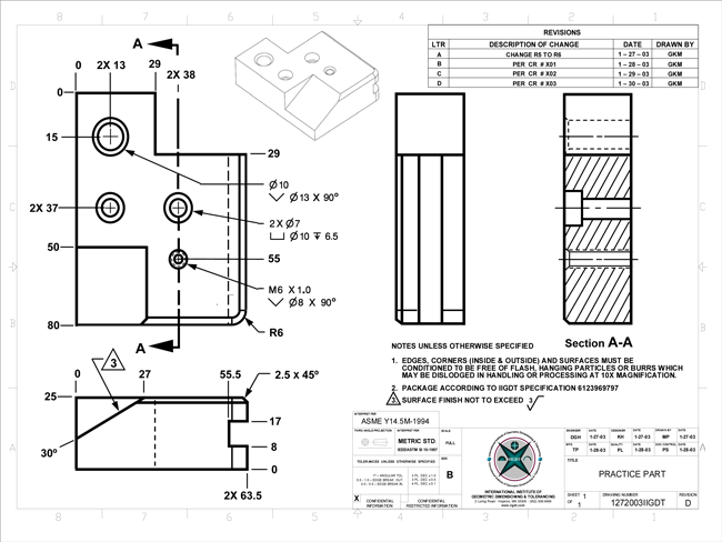
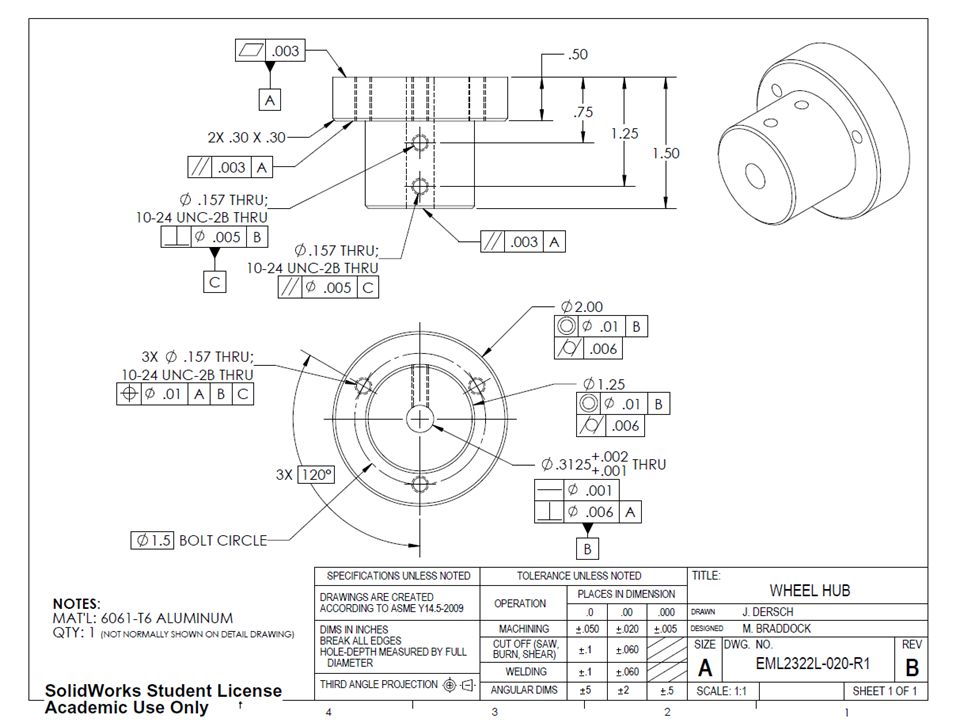
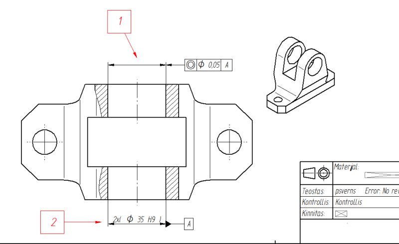
Geometric tolerances geometric dimensioning and tolerancing gd t is a system for defining and communicating engineering tolerances.
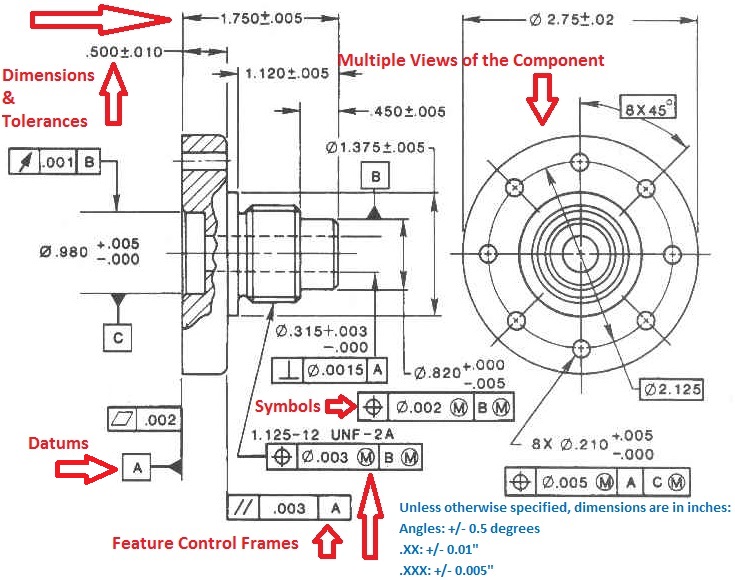
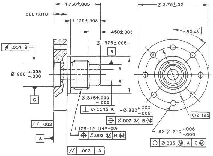
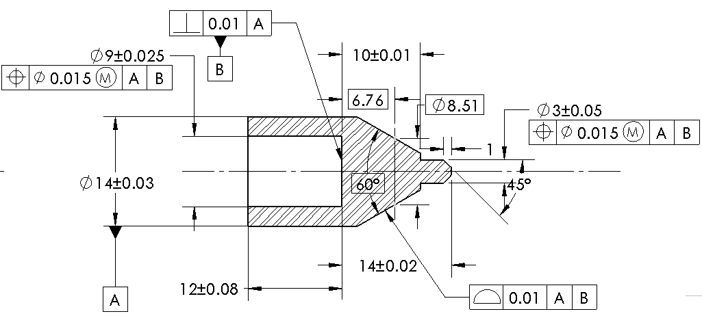
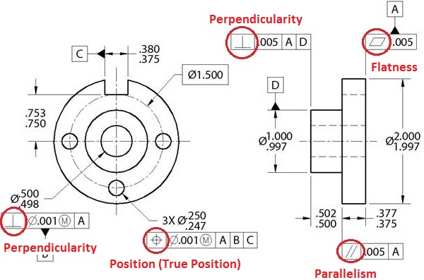
Mechanical gd t drawing. It tells the manufacturing staff and machines what degree of accuracy and precision is needed on each controlled feature of the part. Department of mechanical engineering and mechanics how are tolerances specified size limits specifying the allowed variation in each dimension length width height diameter etc are given on the drawing geometry geometric tolerancing allows for specification of tolerance for the geometry of a part separate from its size. Gd t is used to define the nominal geometry of parts and assemblies. Geometric dimensioning and tolerancing is a system for defining and communicating engineering tolerances.
It uses a symbolic language on engineering drawings and computer generated three dimensional solid models that explicitly describes nominal geometry and its allowable variation. Geometric dimensioning and tolerance gd t is the symbolic engineering language used by mechanical designers manufacturers and inspection personnel to communicate and integrates the functional requirements of the part into the tolerances.
